
The PWM signal is used to control a single ESC or a single servo pulse width modulation signal.
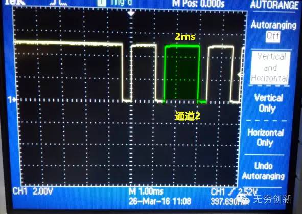
2. The high level duration in each cycle of PWM is 1~2ms (1000us~2000us), which represents the throttle control amount. Generally, 1100us corresponds to 0 throttle in a quadrotor, and 1900us corresponds to full throttle.
The corresponding relationship between PPM and PWM is as follows:
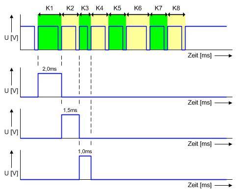
In the above figure, the first row is the PPM signal, and the lower rows are the PWM channel signals. The above figure expresses the correspondence between multiple channels and PPM signal encoding.
The standard PPM signal starts with a low level of 0.4ms. The interval time of the rising edge of the level is used to express the control amount of each channel. After 10 rising edges are generally arranged, the level remains high until the next PPM signal is repeated.
The PPM signal can be regarded as a frame of data, which contains 8 channels of information. The interval of each rising edge is exactly equal to the high level duration of the PWM signal, which is between 1000us and 2000us. The repetition period of PPM is also 20ms, which is also a refresh rate of 50hz. If you haven't understood it yet, there will be a detailed legend below.

The remote control receiver receives the remote control command and outputs the PPM signal. The PPM signal outputs 8 PWM signals through the PPM decoding circuit.
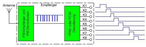
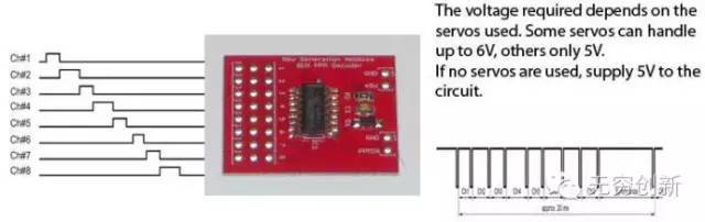
The picture above shows that the PWM signals of multiple channels are converted into PPM signal output through the PPM encoding circuit
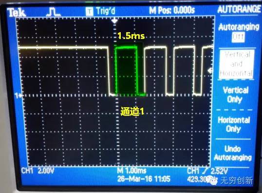
3.2. Channel 1, 50% throttle
When channel 1 is at 50% throttle, the PWM high level time is 1.5ms, and the rising edge interval of PPM channel 1 is 1.5ms. Look at the green instructions.

100 KM long range Video & Data and telemetry for UAV Infofly long-distance image, data transmission, and remote control integrated data link products provide highly reliable communication connections for industrial-grade unmanned systems. Infofly data link products use unique link enhancement technology, which has strong anti-interference performance, stable signal, rich interface types, and excellent electromagnetic compatibility, which can improve the stability and reliability of information transmission of unmanned systems at long distances and maneuvering attitudes. . The product can provide 6Mbps data bandwidth, the longest communication distance is 100 kilometers, supports 1080P HD video transmission, and the image delay is within 280ms. The data link product also provides remote control coach interface, RS232 interface, etc. The airborne end can replace the remote control receiver to directly output the remote control signal, the remote control signal delay is within 40ms, and can be widely used in high-definition image transmission, real-time data interaction and other unmanned System application scenarios.
The InfoFly-SDI data link has a built-in industrial-grade high-performance H.264 image encoder, supports SDI interface video input, realizes three-in-one image transmission, data transmission, and remote control. The ground end outputs a video stream through a network interface and uses computer software to decode The decoding software has local storage and forwarding functions. The end-to-end image delay is at least 250ms.
Features
typical application
Figure 2. Typical application of InfoFly-SDI data link
100 KM long range Video & Data and telemetry for UAV
Working in L, S band
Broadband transmission, air rate 10Mbps
Communication link establishment/recovery time is less than 10ms
Reliable communication and strong anti-interference ability
Excellent electromagnetic compatibility, no interference to GPS, pod and gimbal
Transmission distances of 3, 5, 10, 20, 40 kilometers and more than 50 kilometers can be selected (under visual conditions)
With 1 1080P60 SDI HD image, 4 digital transmission, 2 remote control interface
1 independent PWM channel output on the airborne end, can be used for signal control such as drop and lighting
The ground side adopts software decoding, and the decoding software has local storage and forwarding functions
Optimized transmission of 1080P high-definition video stream with minimum end-to-end delay of 250ms
Can realize point-to-point, point-to-multipoint, relay networking applications
Cold start time 5 seconds.
When users choose SDI interface pods, they need to choose InfoFly-SDI data link radio. InfoFly-SDI has a built-in high-performance industrial-grade SDI interface encoder that outputs H.264 code stream.
Airborne end: SDI interface connects to pod or PTZ camera; COM1 interface connects to flight control data transmission interface for data transmission between flight control and ground station; SBUS1 interface connects to flight control for manual remote control flight; SBUS2 interface Connect PTZ to control PTZ. If the gimbal supports data transmission port control, InfoFly-SDI has 4 data transmission interfaces, and it can also support the gimbal control through the data transmission port.
Ground end: LAN port connects to the computer, receives H.264 high-definition image code stream and performs software decoding. The decoding software has functions such as local storage and network forwarding. The COM1 port is used to connect the flight control ground station to complete the telemetry remote control data transmission; the COM2 port can be used to control the gimbal and pan/tilt; the PPM1 remote control interface is connected to the first remote control through the trainer line to control the flight; the PPM2 remote control interface is passed The trainer line is connected to a second remote control for controlling pods or other loads. If the PTZ on the airborne end is controlled by a digital transmission interface, the ground needs to connect the PTZ control box to the corresponding digital transmission interface.
Contact: Fly Dragon Drone Tech.
Email: frank at dronefromchina.com
Add: NO. 9 Dayu Road PiDu distric, ChengDu 611730, China